Wireless Signals - How Far Can They Go?
When designing and deploying a wireless network, there are several factors to consider. Most manufacturers of wireless access points and routers indicate a typical range that their equipment can provide. Depending on the type of antenna used and the physical location of the access point or router, the range may vary significantly. Wireless Network Design Rules It is important to consider obstacles such as walls, ceilings, furniture, and electronic interference from machinery, power lines and even microwave ovens as these all play a role in wireless signal reception. In ireless transmissions, reflections (when wireless signals “bounce” off objects) and multipath (when wireless signals travel in multiple paths arriving at the receiver at different times) are as important as signal strength in determining the success of an installation. A signal will also exhibit peaks and nulls in its amplitude and alteration of its polarization (vertical or horizontal) when propagating through walls, ceilings and reflecting off metallic objects. Wireless radios have special hardware and software to deal with multipath and signal level nulls, but if the antenna is in a poor location, the radio will not be able to communicate. When trying to get the best performance in a location with a lot of barriers or reflections, it is important to be able to move the antenna in all three axes in order to minimize the effects of multipath and optimize the signal strength. A good first step is to obtain a layout of the floor plan and then draw in access point locations. You will want to “overlap” the range of the access points so you have complete coverage.
Antenna Position Omni–directional antennas should be mounted as far away as possible from all surfaces including walls, floors, ceilings etc. Additionally all Omni-directional antennas should be mounted at the same height for maximum performance and signal strength.
Grid antennas, typically used for point to point line of sight applications, must point directly at one another for maximum signal strength. Be sure to clear all obstructions that could distort or block the antenna beam.
By replacing the manufacturer's antenna with a higher dBi (gain) antenna you may be able to increase signal strength. Again, multipath and reflection must be considered as stated above. Real Life Testing There is no way to know the exact range of your wireless network without testing it first. Every obstacle placed between an access point or router and wireless PC will create signal loss. Leaded glass, metal, concrete floors, water, and walls will inhibit the signal and reduce the range. The best way to see the actual range and performance is to set up a few access points and use a wireless laptop at different locations in the building. By moving the access points and/ or antennas you will see an increase or decrease in signal strength at a specific location
900 MHz ISM Band Applications
900 MHz Spread Spectrum Wireless LAN
1.2 GHz
1.9 GHz: PCS Telemetry Applications
2.3 GHz: 802.11a, WiFi
2.3 GHz: 2305-2360 MHz WCS band
2.4 GHz: 802.11b, 802.11g, 802.11n, WiFi, Bluetooth, Hotspot
2.6 GHz: 802.16, 802.20, MMDS,WiMAX, NLOS
4.9 GHz: US Homeland Security & Public Safety Program
3.5 GHz
4.9 GHz: Homeland Security Public Safety Services: Fire, Police, Security WLAN / On-Scene Incident Command
5.3 GHz
5.4 GHz: 802.11a, WiFi, RLAN, FWA, WiMAX
5.8 GHz: 802.11a, ISM, UNII, WiFi, Mesh Networks 900 MHz: GSM, ISM, WLAN, RFID
And more...
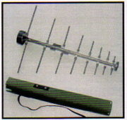
Tactical Log Periodic's
Part # LPD-410
Log Periodic is vertically polarized log periodic antenna operating in a frequency range from 30 MHz ro 1000MHz.
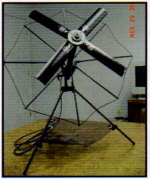
Z-Match Yagis
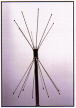
Part # ARA-2576
Manpack foldable tactical antenna fit together with tripod. Extrmely durable harsh environments
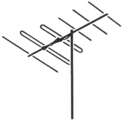
Z-Match Yagis
Part # 5073
Special Application Antennas. Performance, Durability, single or stacked, wide spaced High Band and Low Band.
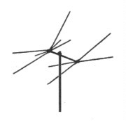
5 Band Scanner Antenna 800-912 MHz UHF-HB
Part # 5094A
Separate receiving elements for low and high VHF and 3 UHF bands, allowing you to immediately tap into all the action.
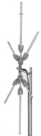
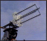
CONICAL YAGIS
Part # 3450
Performance with economy Stacked, Double Stacked X with High Band Stubs. CALL
Polk Omni
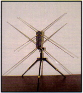
Part # VBC-C3059-2
Ideal for tactical applications when quick deployment of the system is critical. All antenna elements fold around the mast section

Motorola 9000SM
Motorola Canopy 900 MHz SM
Motorola 9000SMF
Motorola Canopy 900 MHz Integrated SM with Interference Mitigation Filter

Motorola 9000SMC
Motorola Canopy 900 MHz SM Connectoriezed
HMA-LTT Helical Antennas
Part # YCA2432LW
138-152 MHz and 310-315 MHz Omni. Elevation beam peak Motorized mechanism. Crossed loop Antenna HF HMA-LTT HMA-LMP
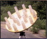
QUAD Helix Antenna
Part # TAS-003QH
Helical Array Antenna INMARSAT F1 Terminals and compact Gimbals SES Earth Station Swept Volume SDM side Lobe Envelope, GT, Axial ratio A/B SES Gimbals.
Gimbal Antenna
Part # TAS-004
Helical Array Antenna INMARSAT F1 Terminals and compact Gimbals SES Earth Station Swept Volume SDM side Lobe Envelope, GT, Axial ratio A/B SES Gimbals.
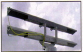
RDA, BHA, BAA and TWA Series
Part # C0711-800
Traveling wave flat antenna arrays Normal Beam radiation accurately perpendicular low profile antenna. Surveillance.
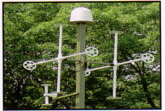
Directive Network Arrays
Part # PNA-2020-100
Directive Network Arrays Cross-polarized PNA exhibits a directional pattern in both vertical and horizontal polarization planes. Direction Finding.
High Gain Fkat Boxhorn Antennas, Panel Rotators, Traveling wave TWA TAA, Printed Element Panels, Commercial Applications, ORBCOMM, INTELSAT, INMARSAT and others.
LEO Satellites WLAN, LMDS, PCS, ISM, LMDS, Doppler and Anti Collision.
Telemetry FTA and FTA-2214 Dual Band High Gain Arrays. Printed Elements, GOES-NEXT, TIROS/NOA, GMS-BPSK,TIROS/NOA Transponders Aperture RADARSAT.

